Bailey bridges are an essential part of temporary and emergency bridge construction. These modular bridges are designed for quick assembly and use in situations where permanent structures aren’t feasible. Bailey bridge design drawings play a crucial role in ensuring these bridges are built correctly and safely.
These detailed drawings guide engineers and builders in constructing the bridge with the right materials and dimensions. In this article, we will explore the importance of Bailey bridge design drawings, how they help in the construction process, and what to look for when interpreting these designs.
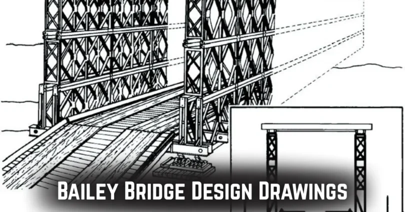
What is a Bailey Bridge?
A Bailey bridge is a portable, modular bridge designed for easy and fast construction, typically used in emergency or temporary situations. It is known for its simplicity and strength, allowing it to be quickly assembled and deployed in various environments.
Definition and Purpose
- A Bailey bridge is a prefabricated structure made up of panels and components that are assembled on-site.
- It is designed to carry heavy loads over gaps, like rivers or roads, without requiring permanent infrastructure.
- Primarily used in military, disaster relief, or temporary construction settings.
- Its purpose is to provide a quick solution for transportation routes when other bridges are unavailable or damaged.
Key Features of a Bailey Bridge
- Modular Design: Made of pre-built panels that can be easily transported and assembled.
- High Load Capacity: Can support heavy vehicles and equipment, making it useful for military or emergency logistics.
- Quick Assembly: The design allows for fast assembly, often in less than a day, using basic tools and minimal labor.
- Durability: Despite its temporary nature, a Bailey bridge is built to last and withstand harsh environmental conditions.
You may also like it:
Techabbey | Innovating the Future of Technology
Educationbeing com | How to Revolutionize Your Learning
Techloomz com | Your Ultimate Guide to Tech Solutions
Bailey Bridge Design Drawings: An Overview
Bailey bridge design drawings are essential blueprints that guide the construction of these modular bridges. They provide a clear visual representation of the bridge’s structure, dimensions, and the materials needed for assembly.
Importance of Design Drawings
- Precise Instructions: Design drawings give clear guidelines on how each component of the bridge should be assembled, reducing the chances of errors.
- Accurate Measurements: They ensure that all parts are the correct size and can fit together properly during construction.
- Safety Assurance: Detailed drawings help ensure the bridge can carry the required load safely, making the construction process more secure.
- Efficient Construction: With the right drawings, assembly is faster and requires fewer workers, making it cost-effective for emergency or temporary projects.
Key Components Shown in the Drawings
- Span: Indicates the distance the bridge will cover, helping to determine the size and number of panels required.
- Beams: Shows where the load-bearing beams will be placed to support traffic flow, indicating the type and material for strength.
- Panels: Illustrates the modular panels that make up the structure of the bridge, specifying how they interconnect.
- Supports and Foundations: Details on how the bridge will be supported on both ends, including soil or surface requirements for stability.
Types of Bailey Bridge Design Drawings
There are different types of Bailey bridge design drawings, each serving a unique purpose in the construction process. These drawings help engineers and builders understand the design, dimensions, and materials necessary for building the bridge.
Detailed Drawings vs. Schematic Drawings
- Detailed Drawings: Provide precise information about the size, dimensions, and placement of every component, including beams, panels, and supports.
- Show accurate scale and placement of all parts, ensuring each piece fits perfectly during assembly.
- Includes information about materials, fasteners, and assembly steps.
- Schematic Drawings: Offer a simplified version of the design, typically used for planning and understanding the general structure.
- Show a basic outline of the bridge with fewer details but enough to understand the overall design.
- Used for early-stage design and communication between engineers and builders.
Load-Bearing Calculations in the Drawings
- Weight Distribution: Design drawings include calculations to show how weight will be distributed across the bridge’s span.
- Helps in determining the strength of the beams and panels to prevent collapse.
- Shows how different types of vehicles or loads will impact the structure.
- Safety Margins: Calculations provide a safety margin, ensuring that the bridge can carry more weight than expected.
- Ensures the bridge can withstand unexpected loads or environmental stress.
- Helps engineers assess the maximum load the bridge can bear without failure.
How to Interpret Bailey Bridge Design Drawings
Interpreting Bailey bridge design drawings requires understanding the symbols, scales, and measurements used in the blueprint. By following a few steps, you can easily read and understand these drawings for accurate construction.
Step-by-Step Guide to Reading the Design
- Start with the Title Block: The title block contains key information like the project name, designer, and revision details.
- Helps identify the specific project and version of the design.
- Examine the General Layout: The first thing to look at is the overall design of the bridge and its dimensions.
- Shows the span length, width, and location of supports.
- Identify the Components: Look for the detailed drawings of beams, panels, and supports.
- Each component is usually labeled with a reference number or name to simplify construction.
- Check the Scale: Design drawings are usually scaled down to fit on paper.
- The scale allows you to convert the dimensions on paper to actual size in the construction.
- Look for Notes and Annotations: Designers often include notes to explain special instructions or clarifications.
- Notes provide important details, like material specifications and installation steps.
Common Symbols and Their Meanings
- Lines: Different types of lines represent various features such as cut lines, center lines, and boundaries.
- Solid lines indicate structural parts; dashed lines usually indicate hidden components.
- Circles: Often represent bolts or holes in the design.
- Helps in determining where fasteners or holes need to be placed.
- Triangles and Arrows: Used to show direction or flow, like traffic direction on the bridge.
- Arrows can also show load distribution or weight direction.
- Dimensions: Numerical values on the drawing indicate size, length, and spacing.
- These values are essential for building the bridge accurately and safely.
Bailey Bridge Design Drawings: Materials and Specifications
Bailey bridges are constructed using specific materials that ensure strength, durability, and easy assembly. The design drawings provide essential details about the materials and key specifications needed for building the bridge.
Materials Used in Bailey Bridge Construction
- Steel: The primary material used for the beams, panels, and fasteners.
- Steel provides strength and flexibility, allowing the bridge to carry heavy loads.
- Aluminum: Often used for lighter, temporary bridges.
- Aluminum is lightweight and corrosion-resistant, making it ideal for short-term use.
- Wood: Sometimes used in older or temporary designs for decking or support.
- Wood can be used for non-load-bearing parts of the bridge structure.
- Bolts and Rivets: Fasteners used to hold the panels and beams together.
- These allow the bridge to be easily assembled and disassembled.
- Concrete: Occasionally used for the foundation or support bases.
- Provides stability, especially when the bridge is intended for longer-term use.
Key Design Specifications Reflected in Drawings
- Load Capacity: The drawings specify the maximum load the bridge can carry.
- Ensures that the design is strong enough to support vehicles, equipment, and other heavy loads.
- Span Length: The design drawings include the distance the bridge will span.
- Helps determine the number of panels required and the type of materials used.
- Panel Dimensions: The exact size of each panel and how they interconnect is outlined.
- Specifies how the modular panels fit together for assembly.
- Support Structure: The position and size of the supports and foundations are shown.
- Ensures proper distribution of weight and stability at both ends of the bridge.
- Construction Method: The drawings may also include details on how to assemble the bridge, including sequence and required tools.
- Provides clear instructions for a smooth and efficient construction process.
You may also like it:
Tech ehla com | Your Guide to the Latest Tech Trends
Dailydishnews | Latest Updates & Top Stories
Newsreverse com | How to Get the Latest News and Updates
Common Challenges in Bailey Bridge Design Drawings
Bailey bridge design drawings, while highly detailed, can present several challenges in terms of accuracy, scaling, and proper execution. Understanding these challenges can help in creating more reliable and efficient designs.
Scaling and Accuracy
- Correct Proportions: Ensuring that the scale of the drawings is accurate to real-life dimensions.
- Even small mistakes in scaling can lead to components that don’t fit together during assembly.
- Conversion Issues: Converting between different units (e.g., millimeters to feet) can cause discrepancies.
- It’s crucial to double-check units and scales to avoid misinterpretations.
- Measurement Errors: Inaccurate measurements in the drawings can lead to improper construction.
- Always verify measurements multiple times to ensure precision and reliability.
- Tolerance Levels: Small tolerances for adjustments in real-life construction may not always be reflected accurately.
- Ensure that tolerances (e.g., for gaps or overlaps) are clearly defined and accounted for.
Common Errors in Design and How to Avoid Them
- Misalignment of Components: Incorrect alignment of beams, panels, or supports can lead to structural instability.
- Double-check that all components are positioned as per the design specifications and ensure proper fit.
- Missing Details: Sometimes, important construction details are left out, like material types or specific assembly instructions.
- Ensure that all components are labeled clearly, and no critical detail is overlooked.
- Overloading Design: Incorrect calculations for load-bearing capacity can result in a bridge that cannot support the intended traffic.
- Use reliable engineering software or methods to verify load-bearing calculations and safety margins.
- Inaccurate Load Distribution: If the load distribution isn’t correctly reflected, it can affect the bridge’s ability to distribute weight evenly.
- Carefully check the load-bearing zones and their alignment to ensure proper distribution.
Modern Uses and Advancements in Bailey Bridge Design
Bailey bridges, originally designed for temporary use, have evolved over time with advancements in technology. These innovations have expanded their applications and improved their efficiency in various fields.
Recent Advancements in Design Technology
- CAD Software: Modern Bailey bridge designs often use Computer-Aided Design (CAD) software to create more accurate and efficient plans.
- CAD allows for quicker adjustments, detailed modeling, and better visualization of the final bridge design.
- 3D Printing of Components: Some parts of the Bailey bridge are now being produced using 3D printing technology.
- This helps in manufacturing precise, lightweight, and customized parts with quicker turnaround times.
- Stronger Materials: New materials, such as high-strength steel alloys and composite materials, are being used to increase the bridge’s load-bearing capacity.
- These materials improve the bridge’s strength while keeping it lightweight and durable.
- Modular Design Improvements: The modular nature of Bailey bridges has been further optimized to make assembly even faster and simpler.
- The design allows for easier transport and quick setup, especially in remote or disaster-stricken areas.
Real-life Examples of Bailey Bridges
- Military Applications: Bailey bridges have been widely used in military operations, especially during wartime, to cross rivers or ravines quickly.
- For example, during World War II, Bailey bridges allowed the Allies to cross rivers and continue their advance, playing a crucial role in the success of military campaigns.
- Disaster Relief Efforts: After natural disasters like earthquakes or floods, Bailey bridges are often deployed to restore vital transportation routes.
- In Haiti after the 2010 earthquake, Bailey bridges were used to reconnect isolated regions, allowing relief supplies to be delivered faster.
- Temporary Roadways in Remote Areas: Bailey bridges are often used for temporary access roads in places where permanent infrastructure is impractical.
- In remote regions of Africa, Bailey bridges have been used to provide crucial transportation links, especially in areas without existing road networks.
- Urban Infrastructure: Some modern Bailey bridges are used in urban planning, especially when constructing temporary access points during large-scale infrastructure projects.
- During the construction of the Dubai Metro, Bailey bridges were used to provide access over roads and waterways, ensuring minimal disruption to the city.
Conclusion
Bailey bridges are a vital solution for quick, reliable, and temporary crossings, especially in emergency situations. With advancements in design technology and materials, these bridges have become even stronger and easier to build.
Whether used in military operations, disaster relief, or infrastructure projects, Bailey bridges continue to play a crucial role in overcoming transportation challenges. By understanding their design and construction, we can appreciate the value they bring to communities worldwide.
You may also like it:
Autolinkrush com | Your Ultimate Guide to Car Solutions
Greenfield Stadium Pitch Report – Batting or Bowling?